The priority is ensuring that everything flows smoothly and quietly. In hydraulics the throttle is a component with which the speed of movement of consumer units (cylinders or hydraulic motors) can be changed.
The basic principle of a throttle valve is that the flow of liquid in the valve can be influenced by a change in the cross-section of the flow. If the flow of liquid is obstructed at a flow-through point by a reduction in the flow cross-section, resistance to the flow increases. This results in an increase in pressure upstream of the restriction. The law of continuity (flow-through law) states that if a medium flows through a pipeline with different cross-sections, the same volumes flow at the same time. The incoming volume flow Qin is equal to the outgoing volume flow Qout.
The law of continuity:
Qin = Qout
A1 ∙ v1 = A2 ∙ v2
This means that the flow velocity of the liquid in the throttling point must rise. This principle can easily be demonstrated with a garden hose.
We know from fluid mechanics that flow velocity influences the type of flow (laminar or turbulent). At throttling points the flow volume usually changes the flow type and becomes turbulent. Turbulent flow also means an increase in flow resistance and therefore a loss of the energy which is converted into heat. In short: throttling points heat up and the turbulent flow often generates noise.
This know-how can be incorporated into troubleshooting in hydraulic systems if, for example, the oil temperature in a system suddenly rises. The problem could be caused by the retrofitting of throttle valves, internal leakage in valve blocks, or excessive leakage in hydraulic cylinders or hydraulic motors. As well as kinked or compressed hose lines, inadequately sized hydraulic valves, pipes and hoses and their bending radii or connecting parts such as elbows or bends act as unwanted throttles in the system. When fluids flow through significantly narrower sections there is – in addition to the increase in the flow velocity – a drop in pressure in the area of the constriction, followed by a corresponding increase in pressure when the cross-section becomes wider again.
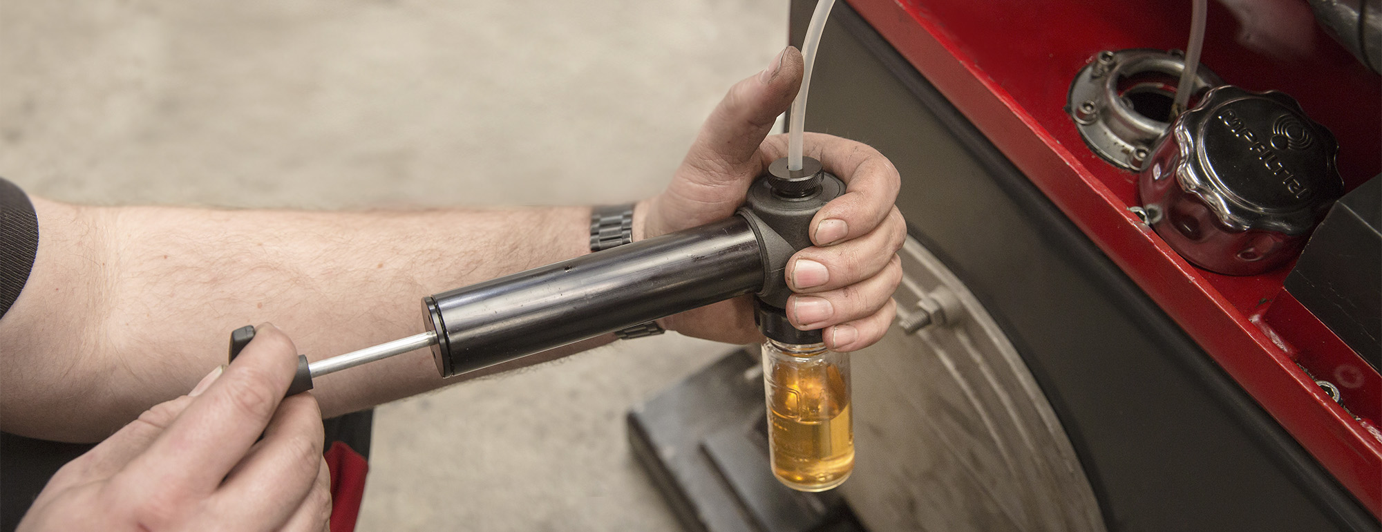
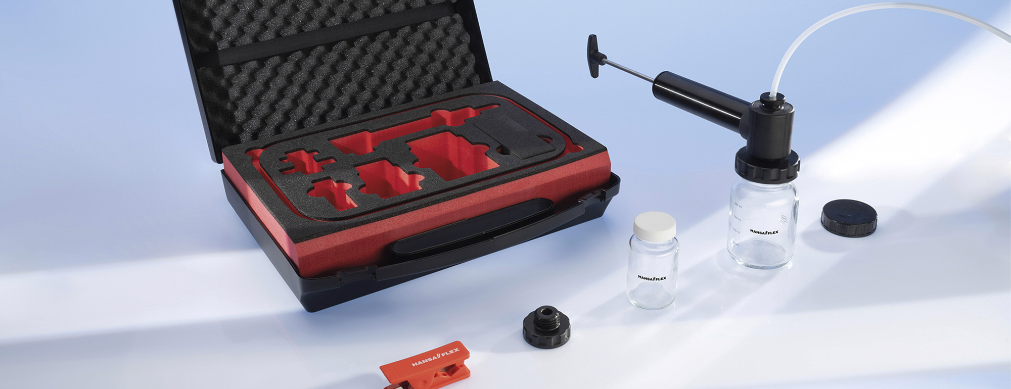
If as a result of the increase in velocity of the volume flow the pressure falls within the range of the vapour pressure of the liquid, the process of cavitation (hollowing out) begins. Outgassing of the medium occurs. Large and small bubbles of steam are formed, which implode and then liquefy again as the pressure rises (increase in cross-section and drop in velocity). The surrounding shell of the steam bubble is accelerated inwards in fractions of a second and so-called microjets with pressure peaks of up to 10,000 bar are formed. Some of them impact against the housing or the inner wall of the hose at high speed right behind the throttling section and literally chisel out material. The freed metal or elastomer particles then contaminate the hydraulic circuit and lead to wear or malfunctions of individual components and even of the entire system. (see Fig. 1 and Fig. 2)
So far, only peripheral factors such as flow speed and pressure have changed when the cross-sectional area is narrowed. According to the law of continuity the volume, i.e. volume flow Q expressed in litres/minute, is as great at the inflow of a line as it is at the outflow. In order for a consumer unit to change the intensity of its movement, the volume flow at the beginning of the line must therefore change: either the volume flow generator (pump) supplies controllably adapted volume flows, or the pumped volume flow is divided into used and discharged volume flow. So what happens to the volume which is not needed?
If only a part of the constant volume flow “Q” delivered by the pump is to reach the consumer unit, the flow cross-section in the throttle valve has to be reduced until the dynamic pressure upstream of the throttle reaches the opening cross-section of the pressure relief valve for the quantity to be discharged.
Hydraulic power generated by the pump from the product of pressure times volume flow (P = p ∙ Q) is divided here into Puse and Pdischarge. In other words, the volume returned to the tank via the pressure relief valve is converted fully into thermal energy.
The throttle as the inflow or outflow control
Under static conditions the following principle generally applies: “one area - one pressure.” If the throttling point is located in the same line as the pressure relief valve (supply throttle), the maximum pressure increase is almost equal to the setting value of the pressure relief valve.
If the throttle is used as a discharge throttle on a differential cylinder on the rod side, the resulting pressure ratio must be taken into account. Beware of the risk of component destruction (see Fig. 3 and Fig. 4).
With hydraulic motors and directional control valves there is no danger of pressure intensification, but even here excessively high return pressures can lead to component damage.
The application, location and type of throttle should be carefully considered and implemented by a specialist. If you would like to find out more about the behaviour of the throttle and other flow control valves, we recommend the fluid technology seminars of the International Hydraulics Academy (IHA): www.hydraulik-akademie.de
-

Jörg Backhaus
Fluid Technology Trainer at the IHA